.png)
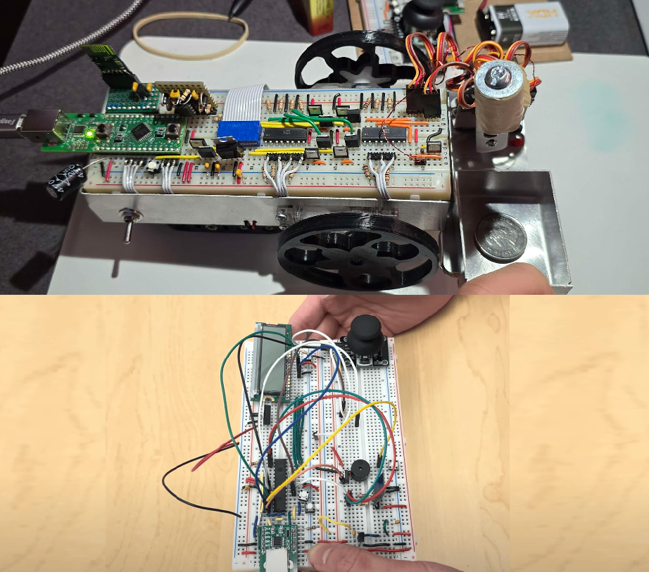
Created my own signal generator that can produce square, sinusodal, and triangular waves. In order to have this work, I used the LM555 timer to produce a square wave. Following the data sheet on page 10, I wanted to create an astable circuit. Astable circuit would allow for constant generation of a signal unlike monostable being singular pulse. Following the guidance provided from the data sheet, I was able to create a square wave. In order to change the square wave such as the duty cycle, you can use this formula:
Duty Cycle = (Ra + Rb) / (Ra + 2*Rb). Do note in my PCB design, I used potentiometer to act as Ra / Rb allowing for multiple duty cycles within the PCB.
With this, you can essentially change the frequency of the circuit since as duty cycle changes, so does the period of the square pulse changes as well. With formulafrequency = 1/Period, you can determine frequency of what you want.
Moving onto the creating the triangular wave, in order for this to work, I would use the original frequency of the square wave and have the frequency enter into a low pass filter. I would made the assumption of Period = R*C -> 1/Frequency = R*C -> Resistance = 1/(Frequency * C). Having isolated resistance, I can use the potentiometer to adjust the resistance to as well change the duty cycle of the triangular wave. Moving onto sinusodial wave, I have a low pass filter along with an inductor ion parallel to a resistor to produce the sine wave. The formula I used to determine the specific impedance (inductance) needed to receive X frequency is through the equation
L = 1/(4*(pi^2)*(frequency^2)*c)
With this equation, depending on the value L, this would produce the frequency of the sinusodal wave. Since I am using a potentiometer, I had to have Impedence of inductor = j*w*L with w = 2*pi*f. And therefore impedance of inductor / (j*2*pi*f) = L. With this information, I can actually determine the combined impedance of inductor + resistor to treat it as total impedance and do this:Impedance of inductor = (j*2*pi*f)/(4*(pi^2)*(frequency^2)*c)
and since we have capacitor be default, and frequency is what we are selecting, we can get impedance of inductor. So therefore with impedance of inductor calculated = (Impedance of inductor + resistor) in parallel, since we know origin impedance of inductor, we can therefore solve resistance to decide which resistor value to select from potentiometer to generate wanted frequency. In terms of testing/simulation, I had used LTspice and had multiple resistor values to act as a potentiometer to see results. Then after confirming the circuit works I began the PCB design.LINK: Google Drive
.png)
The purpose of this was to get some experience with Simulink. So how this works overall (not going into math as theres information in GitHub with a pdf ("imu_data/IMU Simulink Python.pdf") and sources commented in the code of Python that converts the Roll Pitch Yaw into rotational data as it explains more in detail how it works) I used sensor logger application and treated my iPhone 12 as an inertial measurement unit recording calibrated data of acceleration, gyroscope, and magnetometer and used matlab (Simulink) to convert those data into roll pitch and yaw through the process of sensor fusion specifically using an extended kalman filter to get better results. The data of roll pitch yaw is then outputted into a .csv file with all the data over time and I then use Python to show the rotation of my phone overtime.
LINK: GitHub
LINK: YouTube (Demo)

Created Personal PCB Business Card on Altium Designer. 4 layer board with GND layer, PWR layer and 2 additional layers for wiring. MCU used is STM32 (Black Pill Edition) along with electronic components such as a voltage regulator to convert 5V to 3.3V, pushbuttons, and LEDs set as an 8x8 using charlieplexing. Connecting components and ensured traces had enough space from one another to avoid possibility of crosstalk/noise. Used 0.4 mm vias if needed as possible and not making vias too small to avoid cost expenses. Added USB connection to program STM32. Read data sheet of STM32 to configure pin out and used decoupling capacitors to smoothen voltage for needed pin ports.
LINK: Google Drive
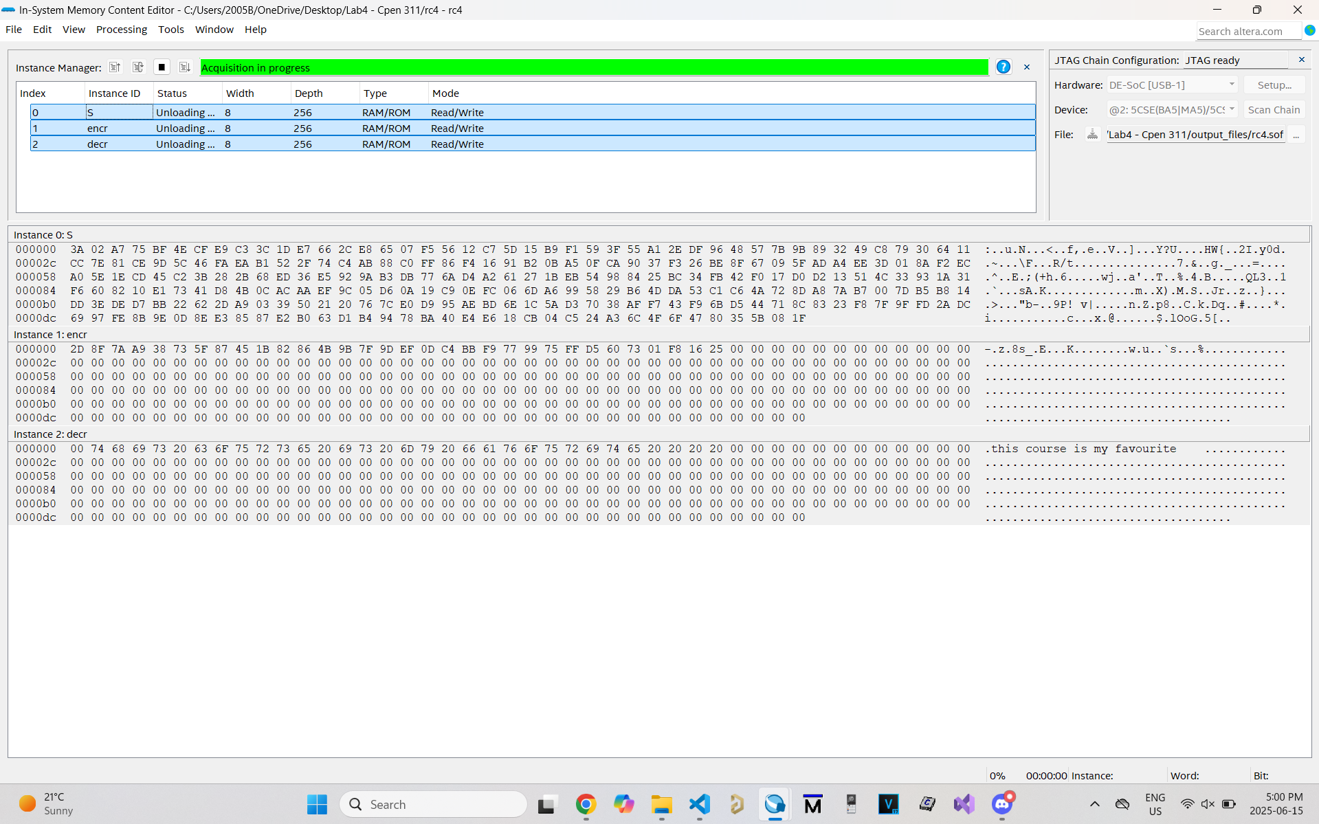
Created FSM to allow user to read data from ROM and put data into RAM. Depending on user input of the 10 switches in the DE1-SoC, this changes the shuffling of how data is stored into the 256x8 bit memory within the RAM. Additionally, I created another FSM which allows for proper decrypting of the data that has been shuffled and stored into RAM. The data that gets extracted from said address undergoes algorithm and is written into another RAM module which is then written into a correct address location allow for user to see the data from Quartus In-System memory editor.
LINK: Google Drive
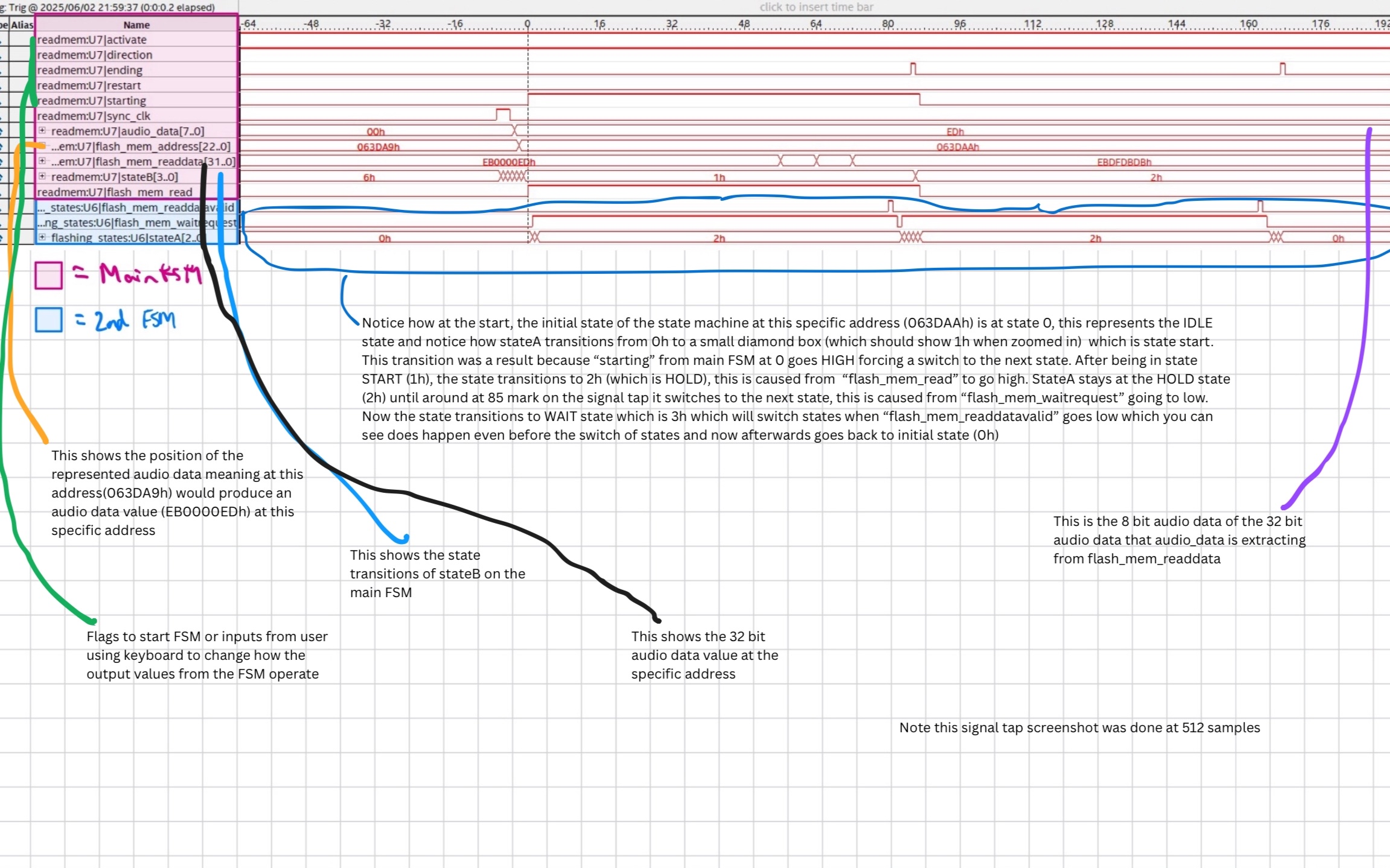
Created an FPGA audio player that extracts audio data from memory. Created 2 FSMs. One FSM for user interface where DE1-SoC is connected with PS2 Keyboard allowing for user to speed, slow, stop, play, and reverse the audio. The other FSM is used to extract audio data at specific address. In order for audio to play properly, data needs to be extracted at a specific clock frequency. Due to the DE1-SoC default 50 MHz clock, I used clock divider to which can also be changed by user via push buttons to extract audio to play properly at correct frequency. Depending # of ticks from new clock from clock divider this can speed or slow audio data. Moreover with extracting data, I need to first read data from address, then store data of X bits to data module which plays audio data at address. Additionally, user input from PS2 Keyboard serves as flags to continue or stop or change process of FSM for proper execution of playing audio based on input request. With debugging, I wrote test benches, used modelsim to view waveforms, used signal tap to see real time audio data extraction.
LINK: Google Drive
Created coin picking robot in groups of 6 that can pick coins up autonomously or be controlled through a remote control that sends signals via UART through master-slave configuration.
Autonomous: Used EFM8 and wrote C key to program the coin picking robot. In order for this to work, we made use of H-Bridge for DC motors to move via PWM. We used optocoupler to power the motor which controls the sequence for picking up the coin (robot arm). We used optocoupler as voltage for motors of wheels and voltage for motor of robotic arm ran at different voltages. In order for the coin picking robot to detect coins and when to pick coins up, we attached inductors where when close, this causes an induced current which as a result, the feedback from the inductor goes into data to the EFM8 and depending on value range makes the robot automatically pick coins up. Additionally, the robot picks coins up within a border that is supplied with a square wave voltage and since the induced current results in a stronger range, the robot randomizes itself and turns for a period of time via timers.
Controlled: Used ATMega328P to act as the control for the robot. This allows sending commands to EFM8 via JDY40 radio using UART protocol. Depending on joystick position, this causes voltage range which dependant on the range would send a char. For example 'w' = forward, 's' = backward, etc. We were able to debug via PuTTY seeing real time transfered data.
LINK: GitHub
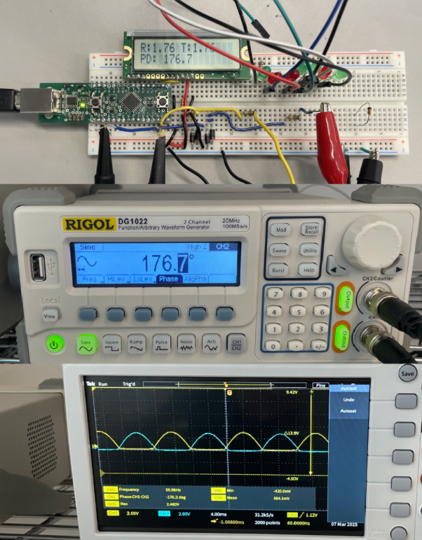
Worked with a partner to assemble electronic components along with writing embedded C in order to measure Vrms, and Phasor Angle Difference from the two waves generated from the oscilloscope. In order to determine Vrms, we first had to receive voltage from pins attached to oscillator which goes into a function "Volts_at_Pin" and returns a 14 bit value which represents the voltage value in bits. To determine the period, we would have the voltage at pin go to 0, and when it goes to 0 we would activate timer 0 which would start timing the period until the voltage at the pin goes back to 0 again as it is a wave that oscillates high and low in a sin like wave. As timer begins, "TH0" (increments UPPER 8 BITS) and "TL0" (increments LOWER 8 BITS) and as timer stops, the TH/L stops incrementing and feeds to formula to get clock period. To determine the timing difference between the two waves, we would have leading voltage pin to rise (positive), and this would start the timer. When the lagging voltage rises (positive), this stops the timer. This info allows us to determine the timing difference between the two phasors. With this info we can determin
Period = clock period * (12000)/(SYSCLK) Note: 12000/sysclk allows UNITS in ms (miliseconds) because each incrementation of Timer 0 (for TH0 and TL0) happens every 12/SYSCLK
Timediff = clock time diff * (12000)/(SYSCLK)
Phase Diff = (Timediff/Period) * 360
Additionally, Vrms and Vtest (2 phasors) are determined (Voltage of pin)/sqrt(2) and all results are displayed onto an LCD
LINK: GitHub
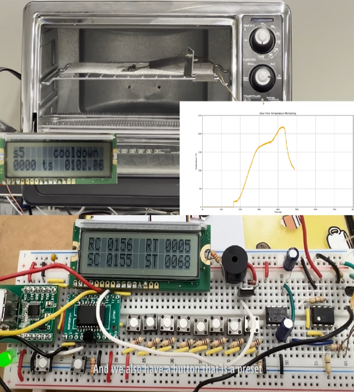
For the Reflow Oven Controller projecs working in groups of 6, we designed a temperature control system using the N76E003 microcontroller programmed in assembly. The system used a finite state machine to step through the five stages of a typical reflow process: preheat, soak, ramp-to-peak, reflow, and cooldown. Temperature feedback was obtained from an LM335 sensor referenced against an LM4040 voltage reference to ensure accurate readings. A PWM output controlled the heating element to follow the temperature curve smoothly, while a 16×2 LCD displayed the current temperature, process state, and elapsed time. Pushbuttons allowed adjustment of target temperatures and durations for each stage, and a buzzer provided an audible alert each time the process changed states. An emergency stop feature was included to shut down the system if the temperature failed to increase at the expected rate. We also created a Python serial interface that plotted live temperature data as a real-time strip chart for visual monitoring.
LINK: GitHub
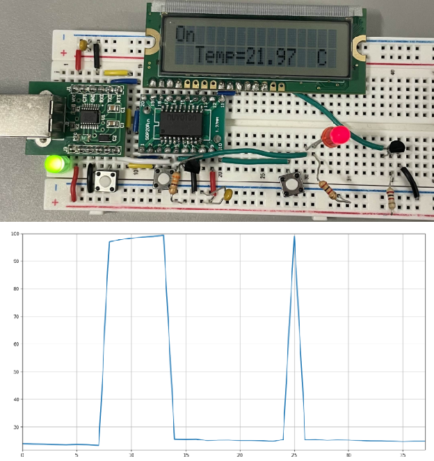
Created a temperature sensor assembling electronics and using the N76E003 in Assembly to determine termperature and display onto LCD. Had Python program to display temperature of sensor in real time.
The example of Python strip chart (x-axis time, y-axis temperature) shows temperature spikes because I used soldering iron heated at 100 degrees celcius and touch pin of temperature sensor.
LINK: GitHub
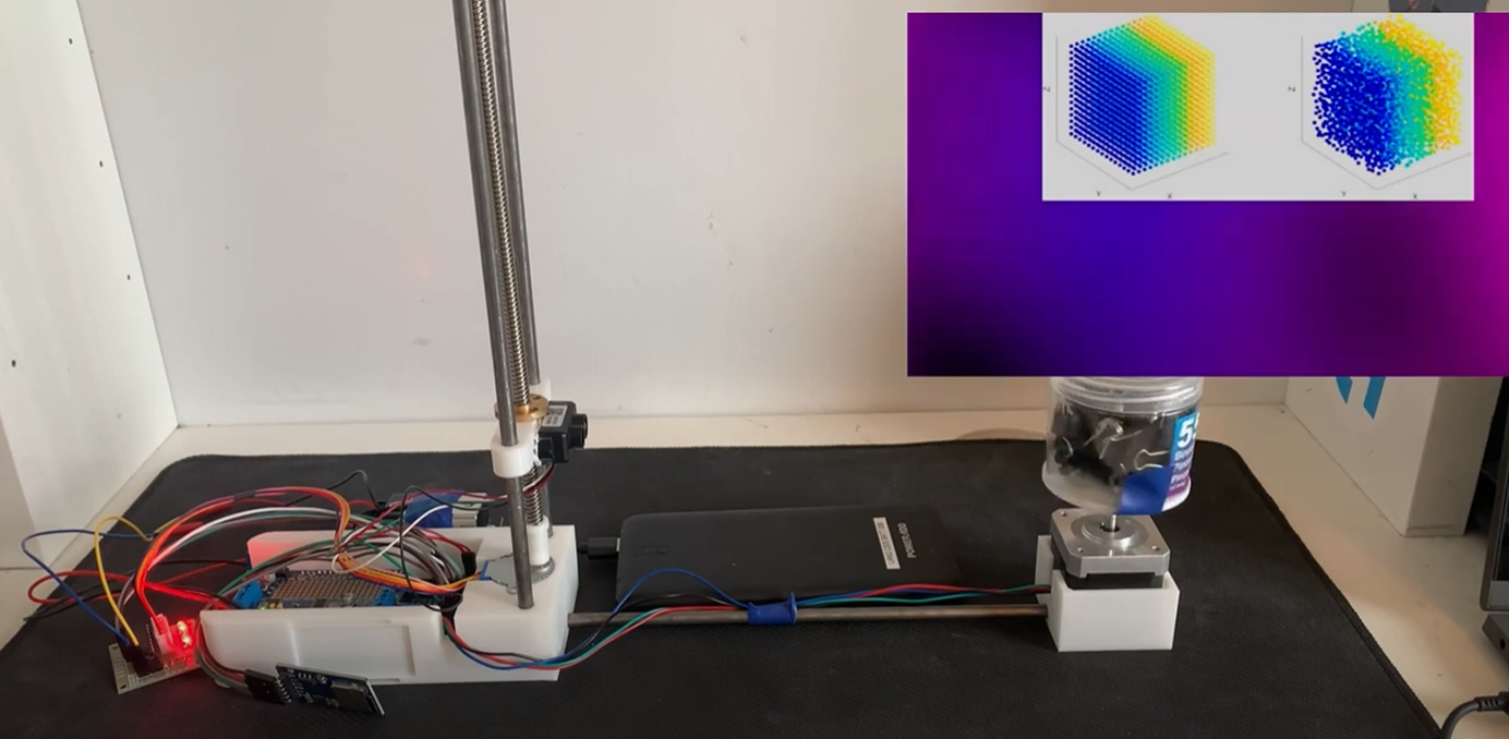
Worked in groups of 4 and used Arduino code and Python. To start, we used Arduino code to scan the data points with LiDAR from the object and printing it onto a file. The code involved the usage of programming the motor to move upwards as we initially had the LiDAR in contact with the lowest level parallel to the object. After scanning a number of samples from the usage of a for loop when the loop process is done the motor would adjust the position of the LiDAR to move upwards to scan the next points of data from the object at a different position. After the adjusting of the LiDAR from the motors is done (reached peak level/height) we would stop the process of scanning data from the LiDAR. Moving onto Python code we used Python code to extract data from the file. From the file we can extract each set of value from x, y and z which may represent one set of value. We can continue to extract all points from the data file in which we will then output the data to create a .ply file which allows us to have a 3D view of the scanned objects with each point that was scanned from the use of LiDAR.